Comprehensive push-button start
#11
you want regulators anyway because voltage fluctuations can have an adverse effect on logic circuits. if you can, test your circuit while varying the supply voltage. make sure a changing supply voltage doesn't cause a circuit to change state.
do you drop again to 5V for the logic? can you get buy with just 5V for everything? that works out well for both a diode and a voltage regulator. a fuse is also a good idea - better to pop a fuse than burn out a trace
do you drop again to 5V for the logic? can you get buy with just 5V for everything? that works out well for both a diode and a voltage regulator. a fuse is also a good idea - better to pop a fuse than burn out a trace
#12
you want regulators anyway because voltage fluctuations can have an adverse effect on logic circuits. if you can, test your circuit while varying the supply voltage. make sure a changing supply voltage doesn't cause a circuit to change state.
do you drop again to 5V for the logic? can you get buy with just 5V for everything? that works out well for both a diode and a voltage regulator. a fuse is also a good idea - better to pop a fuse than burn out a trace
do you drop again to 5V for the logic? can you get buy with just 5V for everything? that works out well for both a diode and a voltage regulator. a fuse is also a good idea - better to pop a fuse than burn out a trace
#14

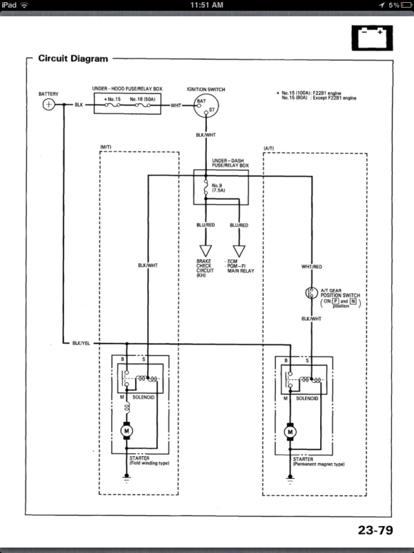
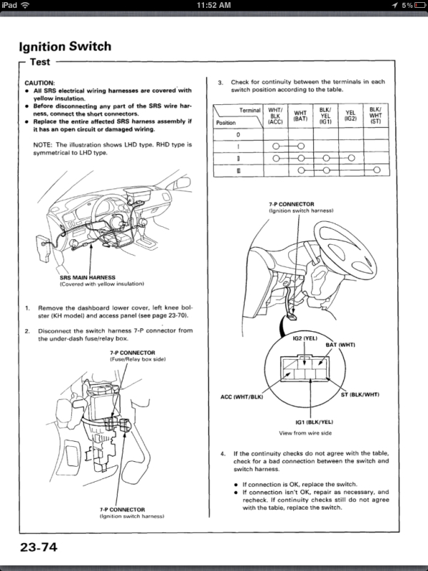
The wire coloring is here

#15
So I got the whole thing working in the car today. I will put up a video as soon as I put the car back together. Thanks for helping me out throughout the whole process. I don't think it would have worked as flawlessly otherwise
#16
excellent project and congrats! it's great to have an idea come together. did you end up using a transistor to control the relay? i'll usually just have the output from the circuit come into the base then let the collector-emitter path switch the relay coil to ground.
#17
Haha, that's exactly what I did. I used the tip120 npn darlington to flip all the relays. This was my first all analog project. Every project I do I decided to use microcontrollers to control everything. Thank you for all your help. I almost have everything back in the car so expect a video soon.
#18
Quick video of the push button start. I want to thank keep_hope_alive for all the help
Push button video
Push button video
Last edited by shehadehd; 09-25-2012 at 03:56 PM.
#19
Quick video of the push button start. I want to thank keep_hope_alive for all the help
Push button video
Push button video
excellent work. very cool project. nice start button.
my input would be to not have the presence of the transponder immediately turn on ignition/accessory power, but instead to have that enable the ability to turn on ignition/accessory power - such as the button up top you use for shutdown.
starting would be placing the transponder in range, enabling the ignition/accessory, then pushing start.
you should add to the video what happens if the car is in gear, or if the brake needs to be applied, etc.
i agree having an accessory only option would also be nice - so radio on without ignition on.
overall, awesome job.
and yes, i do like the interior work.

Thread
Thread Starter
Forum
Replies
Last Post
trijoon
General Tech Help
20
11-26-2010 12:08 PM


